Demonstration
Parts:
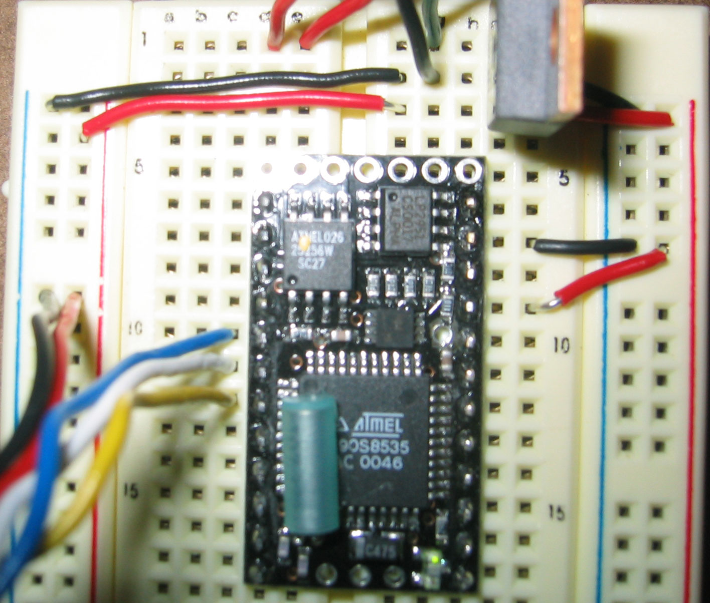
- BX-24 Microproccessor
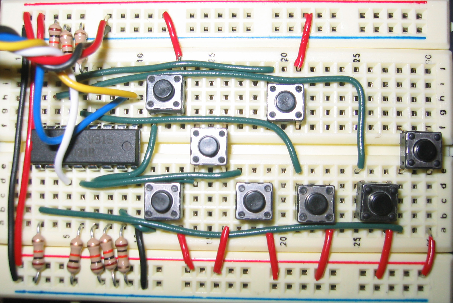
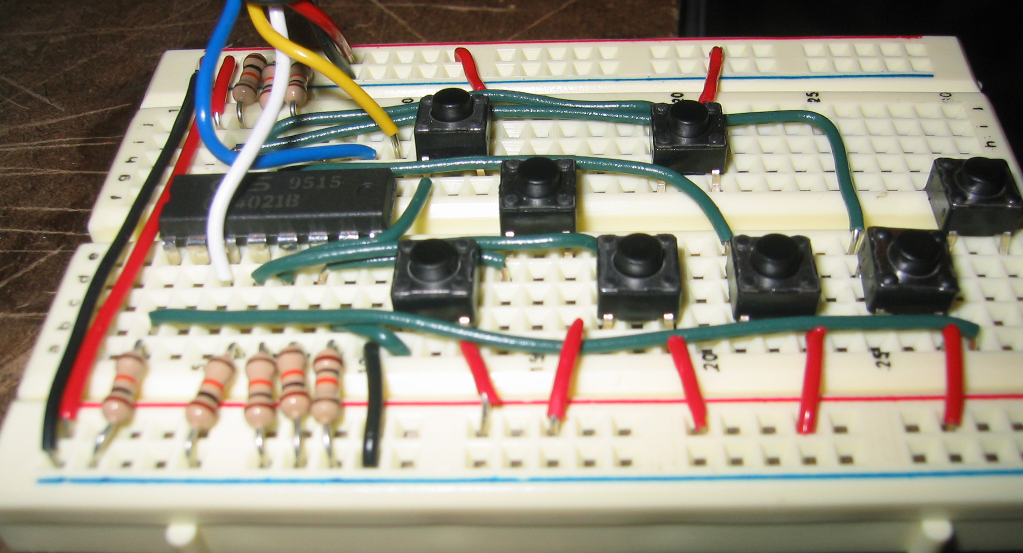
- Shift Register - CD4021BC
- 8 Switches
- 10K Resistors
Hookup:
- BX pin #8 to Ground
- BX pin #18 to +5V
- Each switch has a 10K resistor connected to it in series out from the register pins.
- I didn't to daisy chaining the registers, but in order to do so, all of the pin 10s on the registers should be connected together. All of the pin 9s on the registers should be connected together. Pin 3 of chip one, should go into pin 11 (serial in) of the second chip. Pin 3 of the last chip should go into pin 6 of the BX.
| CD4021BC | Output | ||
| pin # | function | pin # | function |
| 7 | Parallel In #1 | Switch #1 | |
| 6 | Parallel In #2 | Switch #2 | |
| 5 | Parallel In #3 | Switch #3 | |
| 4 | Parallel In #4 | Switch #4 | |
| 13 | Parallel In #5 | Switch #5 | |
| 14 | Parallel In #6 | Switch #6 | |
| 15 | Parallel In #7 | Switch #7 | |
| 1 | Parallel In #8 | Switch #8 | |
| 10 | Clock | 5 | BX-24 |
| 9 | Serial | 7 | BX-24 |
| 3 | Buffer Out | 6 | BX-24 |
BX-24 programming:
This program reads the input from eight switches.
const clockpin as byte = 5
const datapin as byte = 6
const loadpin as byte = 7

dim sq1 as boolean 		'input A0
dim sq2 as boolean		'input A1
dim sq3 as boolean		'input A2
dim sq4 as boolean		'input A3
dim sq5 as boolean		'input A4
dim sq6 as boolean		'input A5
dim sq7 as boolean		'input A5
dim sq8 as boolean		'input A5
dim sq9 as boolean		'input A5

dim data1 as byte		'register1
'etc
'etc for all your inputs
'********************************
sub Main()
'main loop

do

	'your code

	'get the inputs from the switches
	call readInputs()

loop

end sub


'*********************************
'sub read inputs()
Public Sub readInputs()

call putpin(clockpin,1)			'set clock pin high
sleep(2)
call putpin(25,0)				'red led on (optional)
call pulseout(loadpin,1.0E-2,1)		'pulse load pin
call putpin(25,1)				'red led off (optional)
sleep(2)
data1 = shiftin(datapin,clockpin,8)		'read first 4021
sleep(2)
'add the following lines if you are daisy chaining registers
'data(2) = shiftin(datapin,clockpin,8)		'read 2nd 4021
'sleep(2)
'data(3) = shiftin(datapin,clockpin,8)		'read 3rd 4021
'sleep(2)

'turning on the following line will give you the
'value of the switches that are being pressed
'debug.print "data input: " ; cByte(data1)

'we now need to read each data bit one at a time and assign it to our chosen labels.
'this a bit laborious, but cut&paste helps.

sq1 		= not(cbool(getbit(data1,0)))		'input A0
sq2			= not(cbool(getbit(data1,1)))		'input A1
sq3			= not(cbool(getbit(data1,2)))		'input A2
sq4 		= not(cbool(getbit(data1,3)))
sq5			= not(cbool(getbit(data1,4)))
sq6			= not(cbool(getbit(data1,5)))
sq7			= not(cbool(getbit(data1,6)))
sq8			= not(cbool(getbit(data1,7)))


'give me the truth table of which switches are on/off
debug.print "squares = " ; cStr(sq1) ; cStr(sq2) ; cStr(sq3) ;
    cStr(sq4) ; cStr(sq5) ; cStr(sq6) ; cStr(sq7) ; cStr(sq8) '; cStr(sq9) ;

'turn on the following as needed for additional registers

'spare		= not(cbool(getbit(data2,0)
'spare  	= not(cbool(getbit(data2,1)
'spare		= not(cbool(getbit(data2,3)
'spare		= not(cbool(getbit(data2,4)
'spare		= not(cbool(getbit(data2,5)
'spare		= not(cbool(getbit(data2,6)
'spare		= not(cbool(getbit(data2,7)
'spare		= not(cbool(getbit(data3,0)
'spare		= not(cbool(getbit(data3,1)
'etc
'spare		= not(cbool(getbit(data3,7)			'input A23

end sub
- Using the CD4021 Shift Register to Expand the BX24 Inputs:
(I can't remember who wrote this, but I pulled it from the Yahoo Forums for BasicX)
(Also, note that there are a few mistakes in this guy's documentation)
http://www.birnboim.com/nyu/pcomp/techresearch/cd4021.doc
- Product information — CD4021BC:
http://www.jameco.com/Jameco/Products/ProdDS/12829.pdf