Demonstration
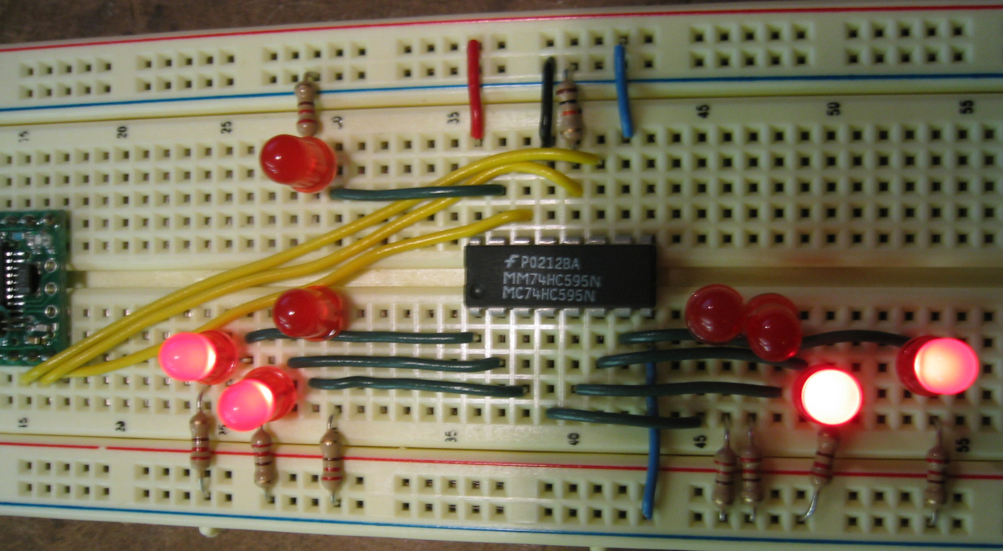
Parts:
- BX-24 Microproccessor
- Shift Register - MM74HC595
- 8 LEDs
Hookup:
- BX pin #23 to Ground
- BX pin #21 to +5V
- Each LED has a 220 ohm resistor connected to it in series.
- In order to daisy chain the shift registers (which is the great thing about them), send the serial out (pin 9) of register one, into the serial in (pin 14) of register two, and so forth. Also, The clock and latch should be sychnronized with either the BX or the previous chip.
- The shift register works from MOST SIGNIFICANT to LEAST SIGNIFICANT. This means that the data in the 'one' column, is going to get bumped first, and the '128' column last (if you are daisy chaining, then the 'one' gets bumped to the '128' of the next register). It might help to draw a diagram of how your data is going to flow, to make sure that you are sending the right info to the right registers.
- SUGGESTION: You should have your 'sequence' of sending bits always fill up the entire register(s) every time. This makes the bookeeping much easier and doesn't require you to flush the registers everytime.
| MM74HC595 | Output | ||
| pin # | function | pin # | function |
| 15 | Parallel Out #1 | LED #1 | |
| 1 | Parallel Out #2 | LED #2 | |
| 2 | Parallel Out #3 | LED #3 | |
| 3 | Parallel Out #4 | LED #4 | |
| 4 | Parallel Out #5 | LED #5 | |
| 5 | Parallel Out #6 | LED #6 | |
| 6 | Parallel Out #7 | LED #7 | |
| 7 | Parallel Out #8 | LED #8 | |
| 11 | Clock | 10 | BX-24 |
| 12 | Latch | 11 | BX-24 with 10K resistor to ground |
| 14 | Serial | 12 | BX-24 |
| 8 | Ground | ||
| 13 | Ground | ||
| 10 | Power | ||
| 16 | Power | ||
BX-24 programming:
This program sends data out to the shift register and 'counts' in binary: 0000_0001, 0000_0010, 0000_0011, etc.
Option Explicit

' The actual pin numbers that you use below, doesn't matter,
' just MAKE SURE that it is properly updated

Dim SerialData as Byte 	      'serial in - pin#12 on BX, pin#14 on 74HC595
Dim Clk as Byte 	          'shift register clock - pin#10 on BX, pin#11 on 74HC595
Dim Latch as Byte             'storage register clock (latch) - pin#11 on BX, pin#12 on 74HC595
Dim NumberOfBits as Byte	  'the number of bits that you are sending to the register

Public Sub Main()

SerialData = 	12
Clk = 			10
Latch = 		11
NumberOf Bits =  8

' create counter variable
dim counterVar as byte

	call delay(0.5)  ' start  program with a half-second delay
do
	' loop for each 'binary' number
	for counterVar = 0 to 255
		' set the clock low.  sync it with the clock of the bx
		call putPin(Clk, 0)
		' set the latch low
		call putPin(Latch, 0)
			' send the data out
			' shiftOut(DataPin, ClockPin, NumberOfBits, Operand)
			' in this case, we are send out the data of the 'binary number'
			call shiftOut(SerialData, Clk, NumberOfBits, counterVar)
			' display the number that we are counting
			debug.print cStr(counterVar)

			' delay, so that we can actually 'see' something
			call delay(0.3)

		' set the latch high
		call putPin(Latch, 1)
next
loop

end sub
- Overview about shift registers including diagrams and GIF animations:
http://www.eelab.usyd.edu.au/digital_tutorial/part2/register01.html
- Links about serial communications including USB and MIDI:
http://www.rdrop.com/~cary/html/serialportdocs.html
- Product information — 74HC595:
http://www.fairchildsemi.com/ds/MM/MM74HC595.pdf
- Application — how to interface a 74HC595:
http://www.kronosrobotics.com/an114/SMAN114.htm
- StampWorks Manual Version 1.2:
http://www.parallax.com/dl/docs/books/sw/exp/23a.pdf - Serial Communication: Shift Registers Research:
http://fargo.itp.tsoa.nyu.edu/~bb400/physicalComp/Serialresearch.html